Loading the Top Chord.
By the late evening of 19 August 1930 the two half arches had been lowered to meet, high above the harbour. There had always been a hinge at the end of the arches where the steelwork met the concrete foundations, and now there was a third hinge at the middle of the lower chord. It was a three-hinged-arch.
The broad concept of the design as specified by Bradfield in 1923, and as detailed by Ralph Freeman in the final design, was a truss arch. The great compressive force, the defining characteristic of all arches, would be carried through the lower chord which was of massive proportions but still too slender to not buckle over the long span. The truss basically stiffens the structure against buckling and, especially near the centre of the arch, both upper and lower chords carry the compressive force. The proportion carried by each is an arbitrary decision by the designer, but it is important that the structure as built be in the same stress state as that intended in the calculations.
The three-hinged-arch is what engineers call a Determinate Structure. That is, the force in any member of the truss is solely determined by geometry and Newtonian statics. Errors in manufacture and variations in member length due to temperature do not change the loads in the members. Once however the hinge at the crown is removed the structure becomes an Indeterminate one where the forces in the members depend on their individual section properties, accuracy of manufacture, and temperature.
Simplistically it could be imagined that the arch had been manufactured complete somewhere else and lifted into place between the bearings whole by some fantastic helicopter. If it was actually a bit long, the ends would have to be forced together to make the arch fit, if too short the arch would have to be allowed to sag and lengthen until it reached the bearings. It either case the forces in the many members would not correspond to the design for which each had been carefully dimensioned to carry safely.
Freeman’s design was fundamentally a simple one. Both upper chord and lower chord would carry about the same force and thus be of about the same size – that is the same amount of steel in the cross section. His argument for this was twofold. Firstly, the balanced truss was the stiffest for the material employed and thus performed better in terms of deflection under rolling live loads – trains and trucks on the deck. Secondly while the primary role of the chords was in the arch truss, they were also the chords of the trusses formed by the upper and lower cross bracing between east and west trusses. These lateral systems resisted sideways buckling of the arch and the considerable wind forces. The top chord needed to be large to maximise the usefulness of the top lateral system. If the design of the arch truss included a lighter top chord, it would have to be have been made heavier for its role in the lateral truss and this would have been wasteful.
Freeman had also calculated that the two-hinged arch was cheaper. It used 96.5% of the steel which might have been used in a three-hinged arch, with proportionate cost savings. This was offset by the cost of the equipment needed to close the arch (£2,000) and the field work required (£10,000) but these figures were only about 1% of the total cost of the arch truss. The two-hinged arch certainly required more calculations but the cost of these was small.
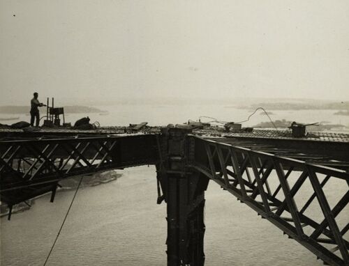
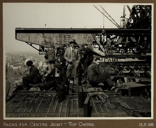
In the Sydney bridge the chords are about equal and soon after closure of the bottom chord, steps were taken to ensure that both chords carried about equal force. This was not absolutely necessary. The Hell Gate Bridge in New York, opened in 1917 and an undoubted model for Sydney, was given no force in the top chord at the time of closure. The last piece of steel in the top chord was simply made a perfect fit but not loaded. Once locked in place the upper chords at Hell Gate do carry subsequently added loads – the deck and traffic – as a two-hinged arch, but do not carry any force from the weight of the arch itself. In the Niagara Falls bridge, built 1897, and the Victoria Falls bridge, built in 1905, stress had been induced in the top chord to carry the self-weight as a two-hinged arch.
The better structural performance of the truss in Sydney notwithstanding, the structure as built had to be made to conform to the design assumptions.
The required force in the top chord depended on the stiffness of all the structural members of the arch truss, any extraneous loads imposed and was very dependent on temperature at any given time. At 40°F it was 3,400 tons and at 100°F only 2,650 tons.
At the time of first contact of the lower chords a force of 14,000 tons was exerted by the tie-back cables at the top of each end post. These forces clearly made the truss not conform to its final in-service state. After 19 August the cables had been de-stressed and removed as quickly as possible, but this took some weeks. The 14,000 ton tensile force in the top chord members near the end posts was far in excess of what those members would carry once the bridge was in service and they had been supplemented with a lot of extra plates for the temporary load condition. These would not be left in the final structure as they were an added and unnecessary load, and also because they were valuable and saleable by Dorman Long if recovered. While they formed part of the section they changed its stiffness and thus the performance of the whole arch. They were quickly made non-structural by driving out the pins and bolts by which they were attached to the permanent section as they were never riveted, but were not all physically removed from the internal spaces by the time of stressing the top chord.
Dorman Long worked quickly after 19 August with the intention of closing the top chord as soon as possible. The great uncertainty was temperature – how could a useful working estimate be made of the temperature of the vast structure when its several aspects were exposed to the sun to different degrees? Temperature, which was measured by many thermometers placed all over the structure, was more even at night, but it was practically impossible to work in the dark.
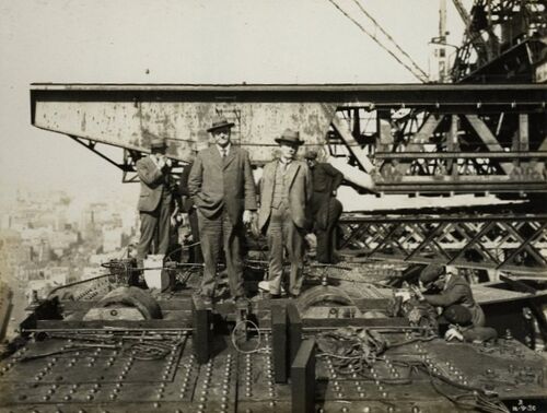
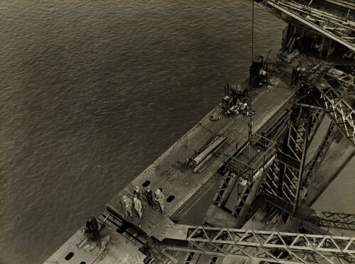
The working plan had been to remove all the tie-back cables and then stress the top chord early in the morning of the next day. By good luck on 8 September 1930 the perfect day arrived, and to their credit Dorman Long were ready. A small number of cables were still attached but only lightly loaded, but the day was overcast and the temperature abnormally uniform. It might never come again, especially with summer approaching, so the decision was made to close the chord that day. Any error caused by the wrong estimation of the effect of the remaining tie-back cables would be small, and far less than that generated by estimating the temperature of the bridge on a less ideal day.
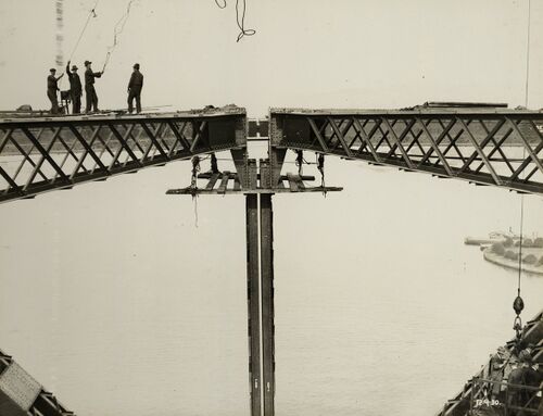
The upper triangles of the centre panels had been erected in the three weeks since closure of the lower chord. The centre post was split, supporting both north and south top chords which had a gap between them of about 2 feet[1]. The halves of the centre post were 5¾[2] inches apart at their lower ends, but virtually touching at the upper ends. The chords were finished with a 1½ inch[3] plate against the webs and against these were placed heavy forgings bearing on a central 10-inch[4] pin. It would be through the webs that the force would ultimately be carried. The flanges of the section were equally strong and capable of carrying the whole force, pending its transfer to the webs. Against the flanges were placed eight hydraulic jacks, 17½-inch[5] diameter with 10-inch[6] stroke – two to each flange of both east and west truss. Following up the hydraulic jacks, in case of any hydraulic failure, were sixteen heavy screw jacks which were kept tight with capstan bars as the hydraulic jacks forced the chords apart. The hydraulic jacks had been calibrated using the 1,250-ton testing machine in Middlesbrough and paired with gauges to maximise accuracy. They had a capacity of 1,080 tons at maximum operating pressure of 4½ tons per square inch, but in the event only carried about 850 tons at about 3½ tons per square inch.
During the morning the pressure in the jacks had been raised to nearly the final figure. The required force was calculated independently by Ralph Freeman and Gordon Stuckey – and they agreed. 3272 tons in each chord, but reduced by 22 tons to 3,250 to allow for the cables still attached. With the required pressure in the hydraulic jacks, and the screw jacks tight, just after 4PM the job was done. Heavy plates had been prepared in the workshops, ready to be planed to fit the exactly measured space behind the forgings. These were machined overnight and the next day and fitted the on 10 September by jacking the ends apart slightly, but with the screw jacks taking the force, and the space unable to change, the bridge was acting as a two-hinged arch irrespective of the temperature of the new day. The actual thickness of these shimming plates was about one inch less than calculated.
During the jacking process the arch had risen a measured 9¾-inches[7]. Calculations had predicted a rise of 10.2[8]-inches, but since the whole process had occupied five hours and there had probably been some change in temperature of the bridge, comparison of the two figures was speculative.
Non-load-bearing light steel covers were later placed over the joint, the two halves of the centre post laced together to make it one, and the central cross member of the upper chord lateral bracing fitted. The bridge was now a two-hinged arch carrying its own weight, the further loads imposed as the deck was added and eventually live traffic loads.


