Henri Mallard was a significant participant in the photographic industry in Sydney in the first half of the Twentieth Century. He spent his whole working life at Harringtons Ltd, a photographic business operating at 386 George Street Sydney from 1878 to 1939. The business was taken over by Kodak in 1933. Mallard joined the firm as a sales representative in 1900, aged 16, and rose to be General Manager by the time of his retirement in 1952.
Henri Marie Joseph Mallard had been born in 1884 at Balmain to French parents, and being home educated, had a strong French accent. With ready access to photographic equipment and skills he was an enthusiastic amateur photographer by the age of 20.
He seems to have had an interest in the work of constructing the Sydney Harbour Bridge during the 1920s with his portfolio including more distant views of the early phases of the work, taken from public vantage points.
In 1929 he approached John Bradfield for access to the work to make a more intimate photographic record but was declined on the basis of safety, Unperturbed, Mallard approached Lawrence Ennis, Director of Construction for Dorman Long & Co, the English contractors for the bridge, and gained approval.
Thus, over the next two years Mallard had apparently unfettered access over the whole site even to the top of the uncompleted half arches. His photos and moving films record the process of erection of the structure, but also more personal and artistic views of workmen at the task.
The major products of these two years were a moving silent film and more than a hundred high-quality still pictures of the construction of the arch and the opening of the bridge. In 1932 this film, or a copy of it, and prints of 116 photos were given by Mallard to the Australian Government, specifically the Upper House of the Parliament, from where Senator John Dunlop Millen (Millen Biography} wrote to Mallard thanking him for the donation. Millen was a mining engineer, foundation member of the Institution of Engineers Australia and one time President of the Institution. At some time in the next few years (Millen retired in 1938 and died in 1941) the film and the photos came into the possession of the Institution.
Institutions such as the Art Gallery of NSW and the National Library of Australia each hold a handful of prints relevant to the Bridge among a wider collection of Mallard’s work. The Powerhouse Museum holds a substantial collection of glass plate negatives, celluloid negatives and prints from the negatives. In 1976 noted photographer David Moore produced 89 prints from what would become the Powerhouse Collection, and about 70 of these were printed in the 1976 book 'BUILDING THE SYDNEY HARBOUR BRIDGE , The Photography of Henri Mallard', by Sun Books Pty Ltd.
The 115 original Harringtons prints held by Engineers Australia are thus probably the major proportion of Mallard’s record of the bridge. A few images which are in the 1976 book do not exist in the Engineers Australia collection.
Henri Mallard died in 1967.
About three-quarters of the prints have captions, probably by Mallard. These have been supplemented by Engineering Heritage Sydney and captions added to those without. The images are presented in the order in which they appeared in the original binding, though this seems to not represent any sensible order. Mallard captions are in bold.
001.The third panel on the southern side being erected. 17 July 1929.
002. The seventh panel on the northern side completed. The southern half arch had stopped construction at the eighth panel to allow the north side to catch up. April 1930.
North Side gradually going forward.
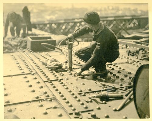
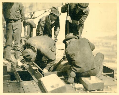
003.Riveter at work near the top of the bridge. Many commentaries refer to hand driven rivets but none were. Two thirds of the many millions (references vary) were driven by hydraulic presses in the workshops and field rivets were closed using pneumatic hammers.
Bolting up the chord. Defective rivets are removed and replaced - 4,500,000 were used in "stich up" this colossal structure. Altogether there are 550.000 separate pieces of steel in the bridge. 1930.
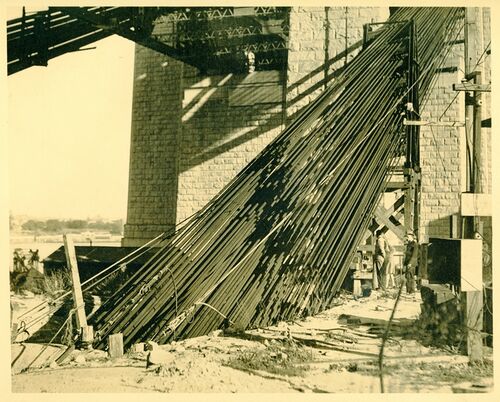
004. The tie back tunnels for the restraining cables were cut deep into solid rock and descended at a very steep angle. The change in direction of the cables was affected by curved steel tubes embedded in strong concrete blocks. Milsons Point 1930’..
Tunnels gave the necessary change of direction to the anchorage cables at this point.
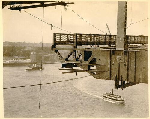
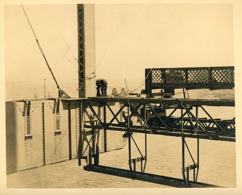
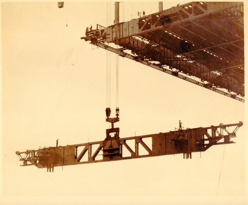
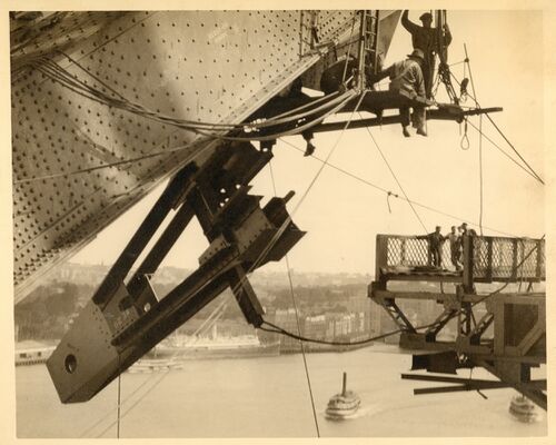
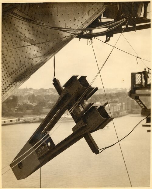
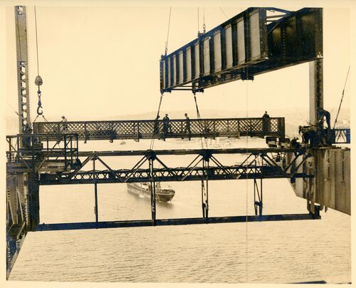
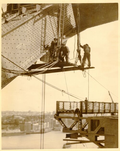
005. Probably the second deck hanger hanging free, with the photographer positioned on the first cross member. The main cross girder in the deck includes a socket which will engage the hole shown in the hanger and the connection will be made with a large pin. Once two cross members are in place longitudinal deck members - stringers - will be fitted to space and brace the cross members. September 1930.
One of the hangers before the pinning together of deck members. Note the hole taking the bolting pin - workmen are busy removing hoisting gear from member.
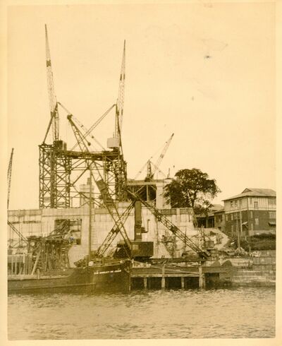
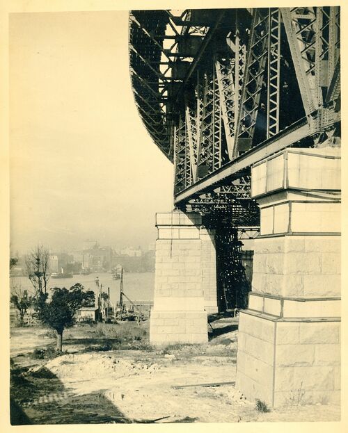
006. An early photo of Dawes Point abutment tower. This would have been taken from a public ferry before Mallard had access onto the bridge site. Note the large opening in the tower front wall to allow the cable-hauled railway through to carry stone, concrete materials and steel components far inland to the extreme end of the site near George and York Streets. The building on the right is pre-existing but was used as Dorman Long's site office. Mid 1927.
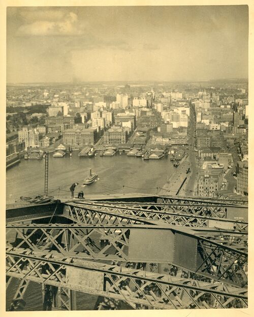
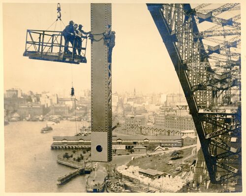
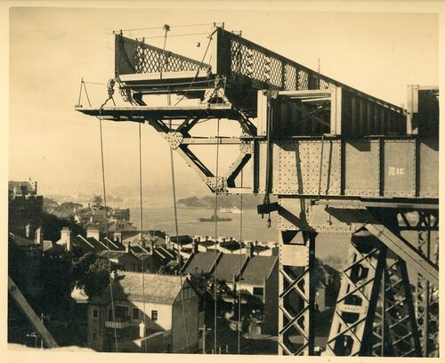
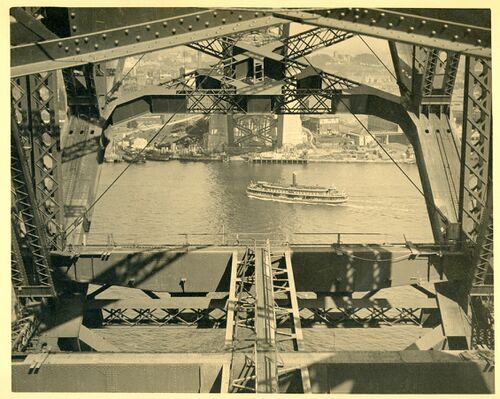
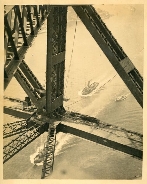
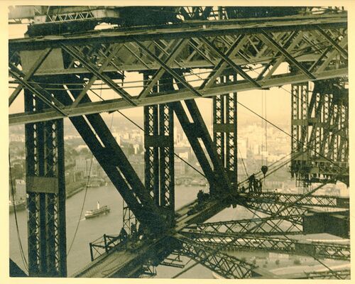
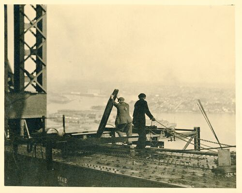
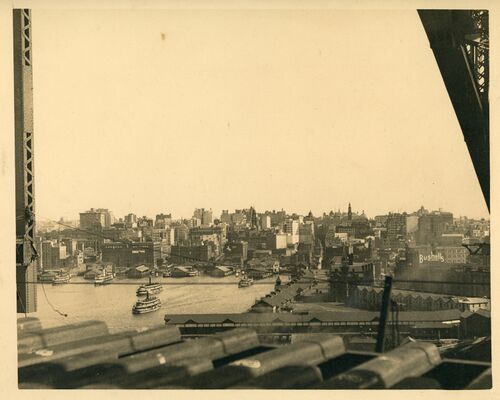
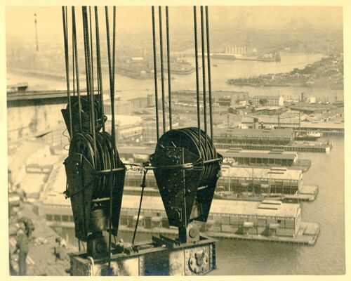
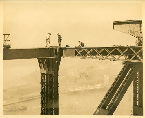
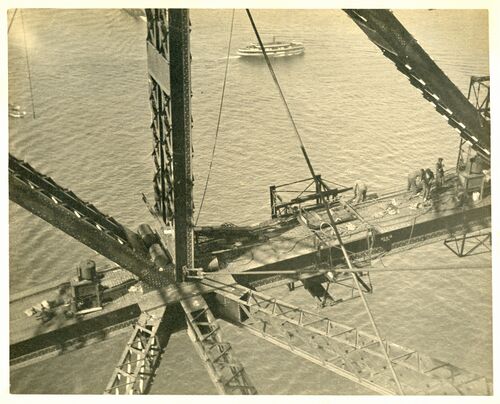
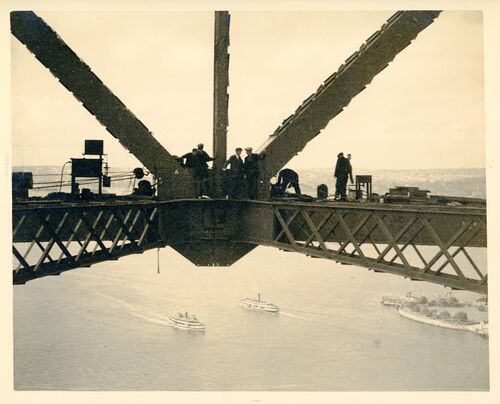
007, The upper chords and upper wind bracing between the arch trusses. This would not be far from the top of the bridge. Circular Quay ferry wharves and the city are seen in the distance. 1930.
The city from the creeper crane nearly 500 feet from highwater mark.
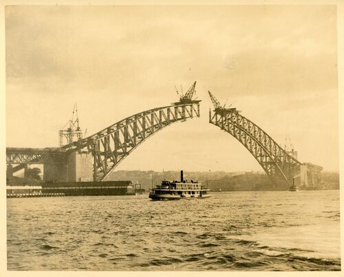
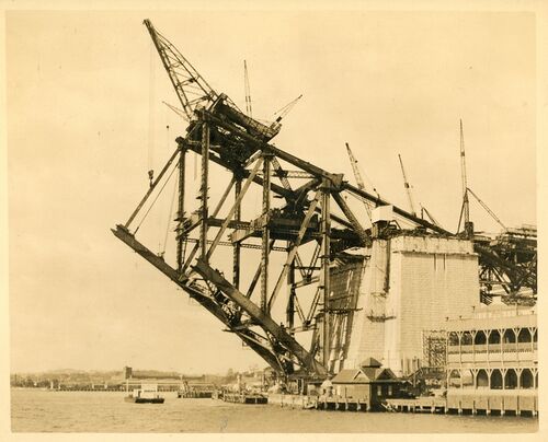
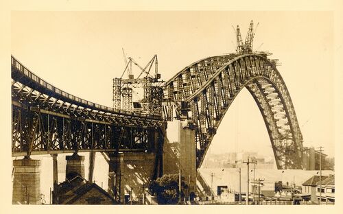
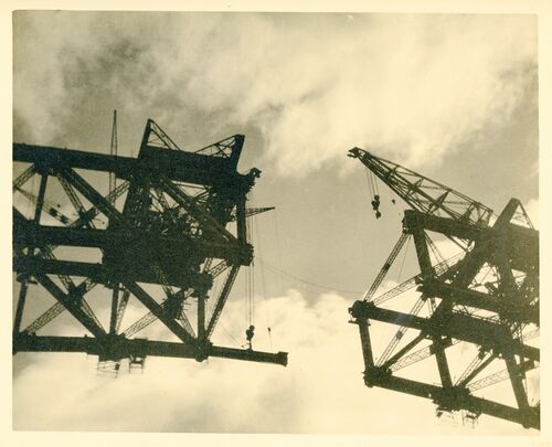
008. The two half arches will meet on 19 August with the last (14th) panel started early in the month. Twelve panels are erected and by this stage, with an experienced crew and lighter, smaller members progress was relatively rapid. July 1930.
The arch nearly completed and held in place by means of cables.
009. This image must have been taken very close to the time the two half arches met in August 1930.
The bridge as it appeared after the arch was complete and before the hangers for the decking were erected.
010 The half arches joined and stressed, and all of the tie back cables removed. Milsons Point, September 1930.
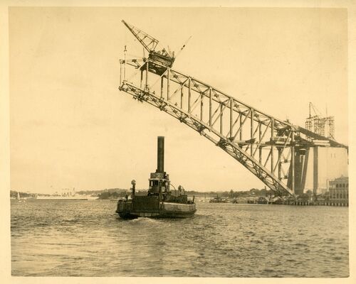
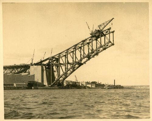
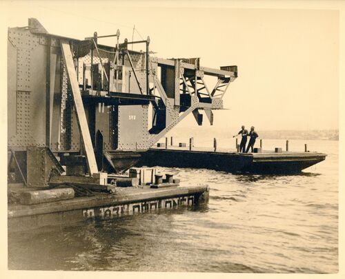
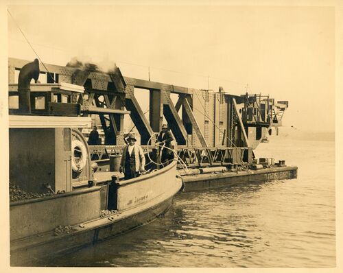
011 The eighth panel on the southern side being erected. Here work will stop for several months while the northern half arch catches up. The northern half arch was built after the southern one so enable to re-use temporary gear such as the crane ramp and benefit from experience gained on the southern side. A steam vehicular ferry is seen in the foreground.
The first panel on the south side nosing its way across.
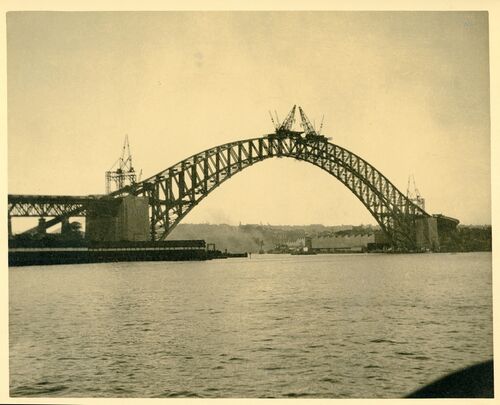
012 The two half arches viewed from Observatory Hill about the time that work resumed on the southern half arch now that the northern side had caught up. April 1930.
Two sets of cables were used on each side of the harbour. Total load supported by cables - 56.000 tons.
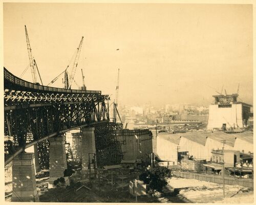
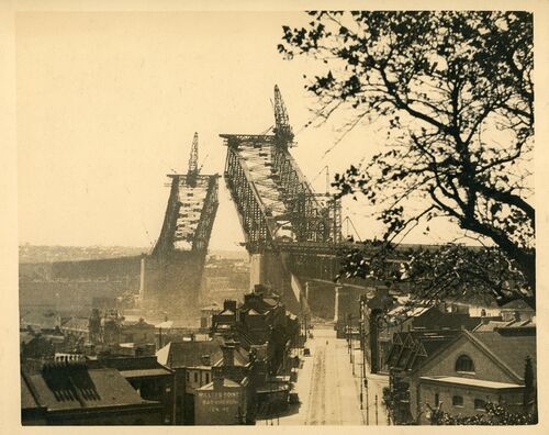
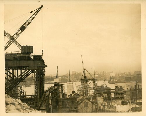
013 An image overlooking the Milsons Point approach trusses probably captured by Mallard before he came to the agreement with Ennis to gain access to the bridge site. In the distance the creeper crane is being erected on the southern abutment towerr, so the date must be late 1928.
014 An image overlooking the vehicular ferry dock at Blues Point probably captured by Mallard before he came to the agreement with Ennis to gain access to the bridge site. In the distance the creeper crane is being erected on the southern abutment tower, so the date must be late 1928.
The pylons constructed, the arch on the south side is on its way.
015: An image overlooking the Milsons Point approach trusses and pylons; only No 6 approach truss has been completed. The bridge workshops are seen on the right of the photo. About August 1927.
Before the huge arch took shape - colossal undertaking. 1650 feet had to be spanned.
016: Dorman Long built all the steel parts of the bridge and associated foundations and pylons. Beyond those limits the approaches were built by the NSW Department of Public Works. This included the concrete arches and retaining walls – at both ends, to reach the deck of the approach spans. Early 1927.
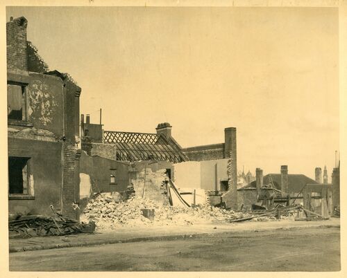
017 Demolishing houses in the Rocks on the Southern approach.
Looking Back towards the city, The cleaning up process goes on This portion of Sydney commonly called the Rocks area. was notorious for its sheltering of the underworld. While these preliminary preparations were going on the contractors were busy making their preparations - these were many. Two huge workshops had to be constructed complete with wharves, accommodation etc.
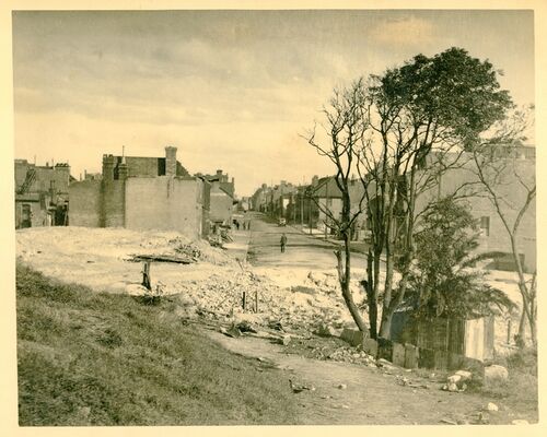
018 Demolishing Prince Street in The Rocks. This street was totally obliterated by the Southern approaches.
Prince Street.
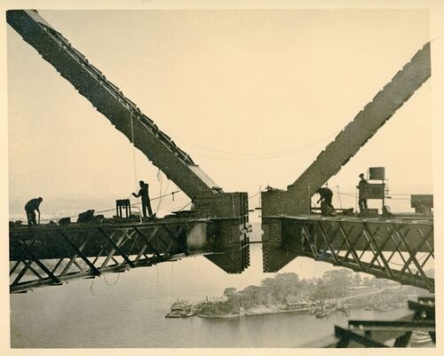
019 Early August 1931. The lower triangle of the 14th panel of the southern half arch, on the left, was completed on 8 August and that on the northern side a few days later on 12 August. The gap, as intended, was about a metre. Lowering the half arches had begun on both sides before the triangle was completed. The two faces first met about 10:00pm on 19 August.
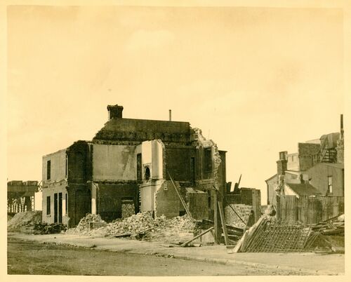
020 Demolishing houses in The Rocks.
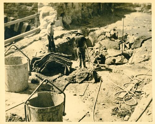
021 Excavation in hard rock by drill and blast. This was generally the method employed for excavation. The heavy rope mats are laid over the blasting to prevent debris from flying outside the site. Spoil is shovelled into the bins for transfer to fill sites. At top left may be arch voussoirs of the old stone bridge over the Argyle Cut. This is a NSW Public Works Department site.
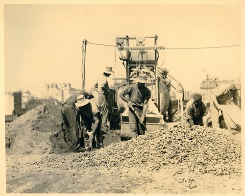
022 Mixing concrete for the Bridge. In the 1920s there were no off site batching plants. The aggregate for the Dorman Long part of the work was crushed granite waste from the Moruya quarry that supplied the cut stone for the facing of the abutment towers and approach span piers; the Public Works Department sourced its materials elsewhere. The site of the work in this picture is not clear.
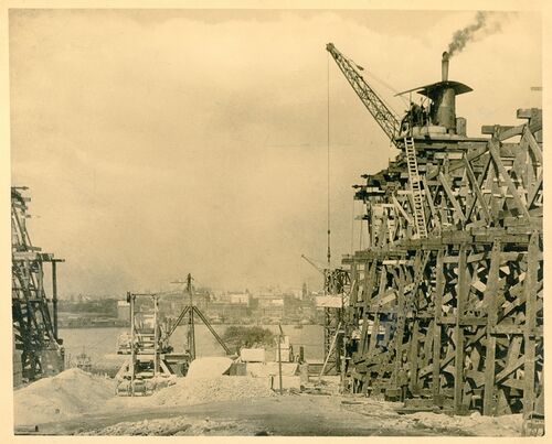
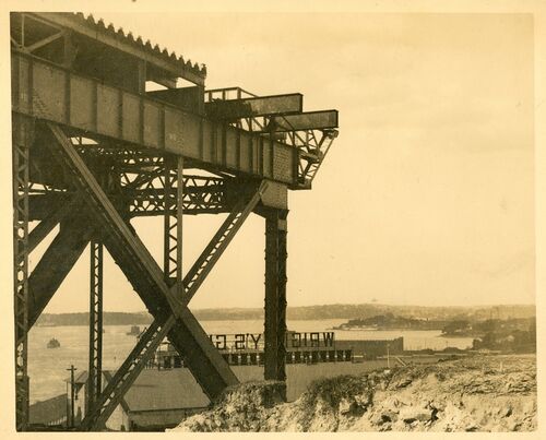
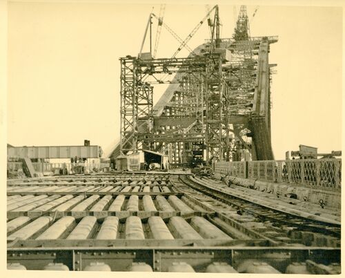
023 'The five approach spans on either side of the harbour are steel trusses, very high above the ground, supported on tall concrete granite faced piers. The working platform for the assembly of the steel trusses was timber falsework which was an engineering task in its own right. The steam crane running on the falsework is solely for the erection of the timber and the concrete piers included within it. This scene is at Milsons Point.
Before the steel work and concrete structure could be erected timber approaches had to be constructed - millions of feet of timber were used in this way.
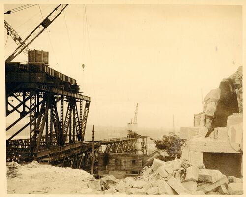
024 'The Northern approach spans amid the demolished remains of buildings in Milsons Point.
Bursting its way through, the steel frame creeps towards the harbour.
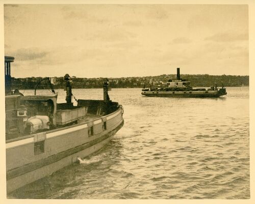
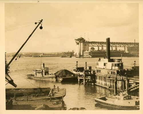
025 Vehicular ferries carried trucks, cars and horse drawn vehicles across the harbour from Blues Point and Jeffery Street to Dawes Point and Bennelong Point. Once the bridge was completed their careers were over.
The punts, their cares nearly finished. They served a good purpose for many years but with the opening of the bridge in 1931 their days of usefulness will be a thing of the past.
026 The curve of the northern approach spans as seen from below.
The sweep of steel resting on huge concrete and granite pillars. So far I have not taken you off the ground - the next slide will take you to deck level.
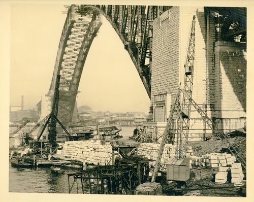
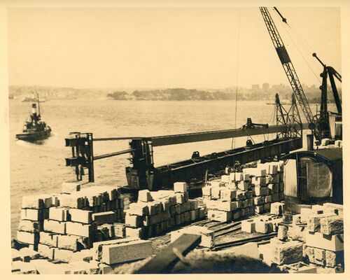
027 By the time the two half arches met in August 1930 the abutment towers were complete with the granite facing to deck level and virtually all the granite blocks for the pylons had been quarried, shipped from Moruya, and stockpiled on the northern and southern shores.
The building goes on - tons of material lying handy for the main structure. May 1930
028 After the arch was closed in August and stressed in September 1930 the suspended deck was largely completed by the end of the year. This view, from the arch with staging suspended from the chord top left, shows a hanger and the deck cross girder.
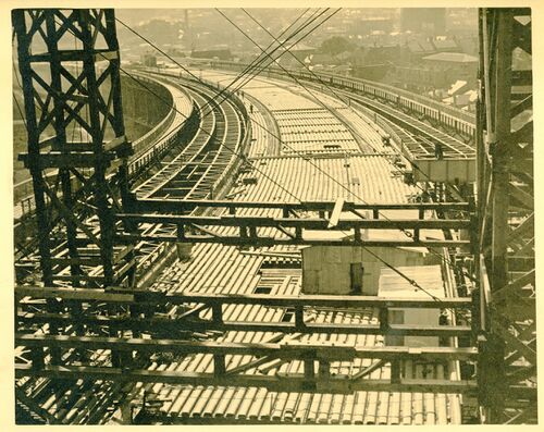
January 1931 Looking down on deck level approach span on north side. The accommodation for traffic will be sufficient for generations to come, provision having been made for four lines of electric railways - six lines of vehicular traffic and two footways, each ten feet wide. When working at its maximum capacity 168 electric trains, 6000 vehicles and 40,000 pedestrians can cross the bridge in n hour - giving room for expanding the population at the northern side of the harbour by nearly another million inhabitants.
029 The northern end of Dorman Long's work overlooking houses in Kirribilli; this was the starting point for their work several years earlier, and the end point of the Public Work’s work reaching out from North Sydney. The image shows the eastern footway. It’s interesting that the two footways on the bridge are each 10 feet wide, while the road lanes are only 9 feet 6 inches..
This pedestrian way - 172 feet from high water mark - will give pedestrians a wonderful view of the harbour and surrounding country.
030 This deck-level image was made in early 1930 before the two half arches had met. The visitors are VIPs on a conducted tour.
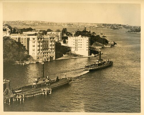
031 The vehicular ferry dock at Jeffery Street with Kirribilli behind. This dock and its road approaches were purpose to replace docks on Milsons Point which were removed to allow construction of the bridge..
This slide and the subsequent ones are views of Circular Quay from deck level.
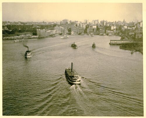
032 Circular Quay and its busy ferry fleet as seen from the bridge deck.
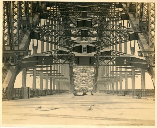
033 Looking down on the gap where the deck is carried though the bridge lower chord bracing system.
Looking down on deck level - width of deck 159' 11 3/4"
3
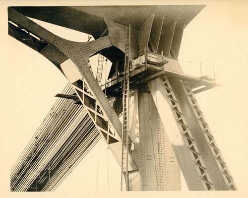
034 The top of the end post from within the bridge truss, with the tie-back cables connected to the top chord.
The end post - beginning of the top chord, showing first diagonal bracing, gusset plates and cables. Height of Post, 187 feet 9 3/16 inches high.
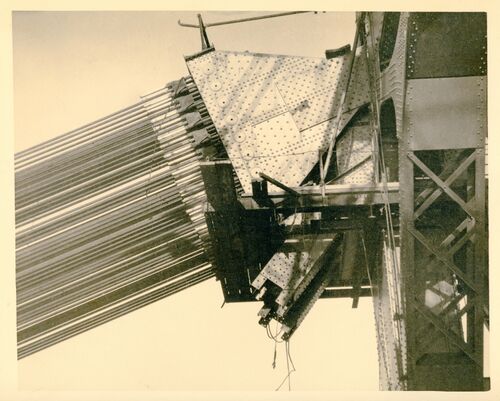
035 The top of the end post from outside the bridge truss, with the tie-back cables connected to the top chord. The truncated girder below the link plate is the remains of a strut to the abutment tower strong floor, used during earlier stages of the erection of the half arch.
Anchorage cables - showing how they were connected to end post. Four groups of 128 cables each cable fitted with a steel socket pin in end connection - 10 inches in diameter - each cable measured 2 3/4 inches in thickness and taking a strain of 14,000 tons per set of 128 cables.
036 The link plate between the 128 tie-back cables and the bridge top chord. Within the spaces between the link plates men could work with hydraulic jacks to lengthen the cables and thus eventually remove them. As the cables were lengthened the two half arches of the bridge moved together until they met.
Group of 128 cables entering anchorage tunnel. These anchorage tunnels on both sides of the harbour had to be driven at an inclination of 45 degrees into the rock. They were "U" shaped in plan and extended 132 feet into the rock, and were lined with corrugated steel plates and concrete. Reinforced concrete saddles at the mouth of these.
037 Hydraulic oil lines and valves driving the jacks to load the cables and eventually release them. In August 1930 as the half arches came together there were three jacks at each corner being shifted from cable to cable about every 20 minutes. It took several days of round the clock work to bring the two half arches together.
038 The half arches about July 1930 with perhaps just one panel each side to be completed. The tie-back cables were supported from the approach truss and from the ground but even under the tension of more than 100 tons sagged a little. The uniformity of this sag was proof of the equal sharing of the massive load between the 128 cables.
Chords taking the strain.
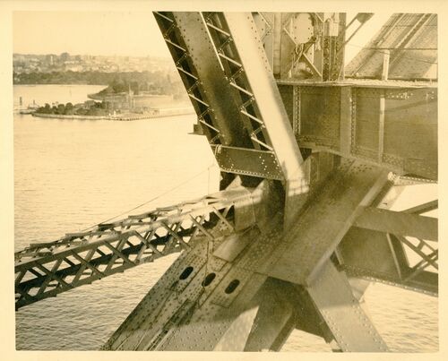
039 The most complicated connection between the arch chord, a truss post and a truss diagonal, lower chord wind bracing, a deck girder and a brace to the long post of the next panel. The three longest posts as the end of the bridge are slender enough to cause concern that they could buckle and are thus stiffened at their mid-length by this light lattice-braced member. The four webs of the main chords create three internal spaces and these are accessible via the dark ovals - manholes. On the top chord the manholes were used as locks for the creeper crane in it travel.
End of third panel, lower chord, showing bracings, chord, diagonal and upright. Also deck support. The three holes in the chord are man holes, permitting workmen free access to interior of chord for riveting etc. NOTE The most complicated portion of the structure.
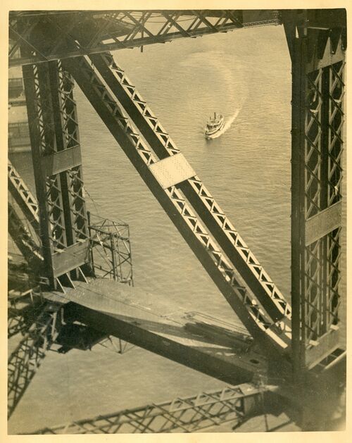
040 A diagonal brace in the truss frame. All members of the frame were built as longitudinal pairs and in some ways the bridge could be considered as having four arch trusses with two pairs immediately adjacent and locked together. To guard against buckling adjacent pairs are strongly linked at their midpoints in case they ever carry a compressive load. Careful inspection of the bridge will show some members, which are always in tension both during construction and under the most extreme service conditions, have no plates at their mid length..
Between the chords - showing uprights, diagonals and bracing booms.
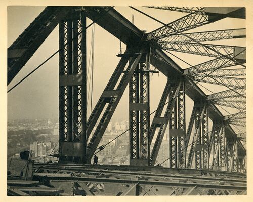
041 Both upper and lower chords are cross braced with double diagonal members and posts between adjacent panel points. These strong trusses (98 feet deep) resist main truss buckling and wind loads.
Another view from the top chord - giving a fair idea of the bracing of the chords.
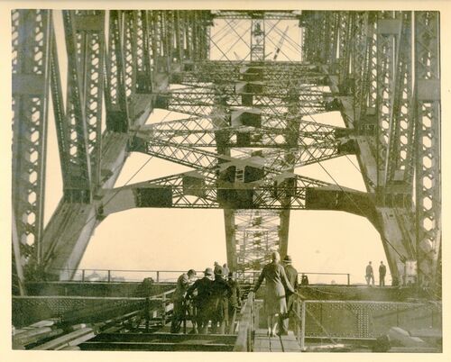
042 Inside the tube of the main trusses and the wind bracing during construction. At this phase sway bracing was provided by opposing tensioned cables at every panel point, to reduce deflection at the ends of the long cantilevers. This bracing was removed once the arch was complete and the bridge now has no sway bracing between the two arch trusses.
A view showing the method of bracing the top chord to the bottom chord, uprights, diagonals and booms. The city is in the distance.
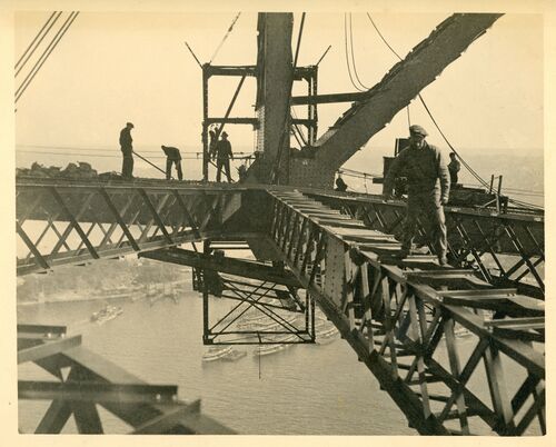
043 Workers are riveting a newly lifted bottom chord member. The diagonal cables at top left are holding the chord, pending the arrival of the permanent diagonal. Little protection against falling off the bridge was provided. The bridge felt stable under foot. Ennis reported standing at the top of the bridge just before closure during a gale. He could see the two half arches moving three inches relative to each other, but had no perception of this through his feet.
Workmen are just as much at home on the cross girders of the bridge s they are on the footpaths in town. Only one man was lost, up to the present, off the bridge and that was purely accidental - a spanner head slipping causing the accident.
044 The chassis of the crane of the thirteenth panel, south ready to erect the 14th and last panel.
The last post on the south side before the two sides of the arch met. Government House in the distance.
045 The erection of one half of the last southern lower chord member on the west side of the bridge on or about 7 August 1930. The creeper cranes could derrick in or out using long screws in their jibs. The southern crane is standing near vertical to lift the heavy chord about half way out the next 60 foot panel. The northern crane is still on the twelfth panel with its jib nearer to horizontal to reach far forward to fit the light post between top panel points - about 60 feet ahead. The northern crane will move forward onto panel 13 soon - it will take about an hour - to be in position to begin erection of northern panel 14 on 12 August.
50,000 tons of steel coming together 437 feet 6 inches from high water mark
046 Inside the tube of the main trusses in mid 1930 with only a few panels left to erect.
047 In September 1930 with the lower chords in contact and carrying the weight of the bridge, the top chords were completed but left with a gap to fit huge hydraulic jacks to stress the top chord so as to share the axial force in the arch trusses between the top and bottom chords as required by the design calculations. Here workmen are fitting one of the jacks.
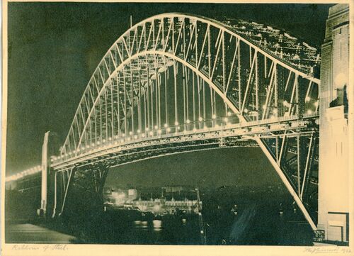
048 The bridge was lit for the first time in early March 1932 just before the opening. This may be that occasion or soon after.
THE BRIDGE AND APPROACHES. THE ACTUAL DISTANCE IS TWO MILES, 33 CHAINS.
049 The road deck of the near completed bridge in early 1932.
THE DECK BEFORE THE OPENING. LIKE A HIGE GIANT SLUMBERING AND AWAITING HE DAWN OF AWAKENING. A GIANT IN STRUCTURES - A GIANT IN COST £5,000,.000.
050 This is probably the central cross girder of the deck. Note the lifting gear to the outside of the hanger. The central cross girder was the only part of the bridge lifted with both cranes. All the other cross girders were lifted at their centre. The footway lattice span has some function at this time in holding the cross girders in their correct position. The light frame in the foreground carries the track for the underhung maintenance gantry which will be fitted later. The heavier laced girder in the background is the chord of the very deep (160 feet) and rigid lateral truss which stiffens the deck in its final form. Note the connection points for the railway stringers which fit between the cross girders. To make the geometry of designing and fabricating these stringers tractable the cross girders are normal to the deck which rises on a grade of 1 in 40 to a central ease over the centre of the bridge. Thus the pocket in the cross girder which receives the hanger is not parallel to the webs. It is a fine piece of fabrication. This being the central cross girder the pocket is perfectly vertical. Temporary lateral cable cross bracing was also provided at this time until the deck with its truss was completed.
This slide shows how the hangers hold the decking in suspension, also giving the idea of the extra height that the pedestrian way is above deck level.
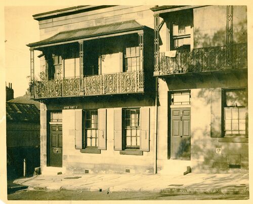
051 A house in The Rocks or North Sydney before demolition to make way for the bridge.

052 The deck of the bridge showing the stringers to carry the railway tracks, one either side of and very close to the hangers. While this arrangement kept the heavy loads near the point of support and thus lightened the cross girder, Ralph Freeman would have preferred the four railway tracks together in the centre of the bridge deck, where some of the load would always be transferred to both arch trusses. The arrangement of the tracks as they are creates the possibility of both tracks on one side of the bridge being heavily loaded with the other two absolutely unloaded, thus distorting the bridge significantly.
053 Workers on the bridge lower chord probably dismantling a stage.
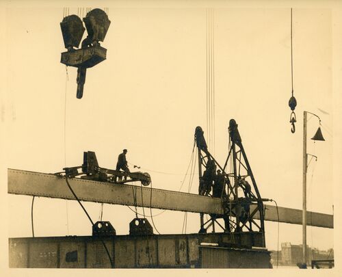
054 The last cross girder being lifted, probably at the norther side (See photo 066) This would have been the last heavy lift of the crane with all remaining sections - deck stringers etc being very light.
The last cross girder weighing 100 tons in mid-air. And by the way, the last heavy lift performed by the creeper cranes.
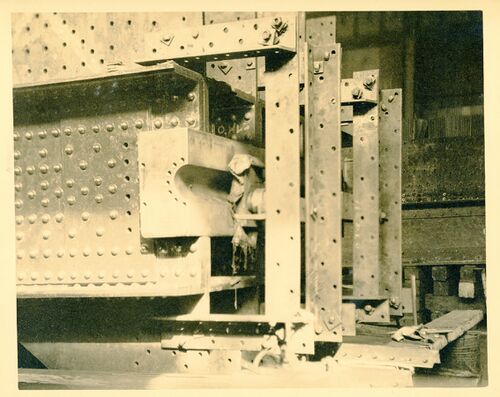
055 The end of both lower chords at the centre joint consists of a steel block bearing on the webs of the chord. Into the block is machined a 10 inch groove to receive a 10 inch pin through which all compressive force in the joint was temporarily transmitted until the half arches were jacked apart and the final members were riveted into position, thus making it a two hinged arch.. Here in the workshops a temporary rig of heavy angles is set up to resist the force of jacks which press the steel block hard against the webs before fixing. This the southern chord member as the set screw hole around the semi-circular groove were used to secure the pin which was lifted with the southern chord.
A close view of one of the carbon steel bearings. Dimensions: width 13 inches tapering to 12 inches, length 50 inches, diameter of pin 9 inches, half pin bearing in south side.
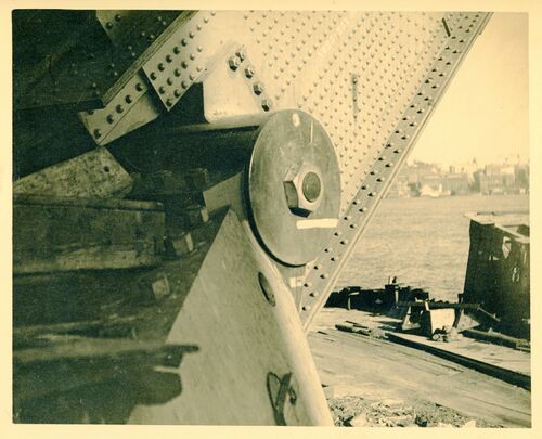
056 The south-east bearing pin at Dawes Point with the lower chord of the arch bearing on it. The pin is 14½ inches in diameter, provided with a threaded extension and securing nut. The circular plate behind the nut is larger than the 14½ inch pin to also cover the ends of the semi-circular bearing casting in which it sits. Below the pin is the 296 ton pyramidal assembly which distributes the concentrated force to the massive concrete skewback excavated deep into the base sandstone’.
This slide shows the beginnings of one of the bottom chords, also one of the four bearing pins with its total weight of 296 tons. The base area measures 21 feet x 24 feet - the height to centre pin is 13 feet 11¼ inches - the size of the main pin is 14½ inches diameter by 13 feet 8 inches long.
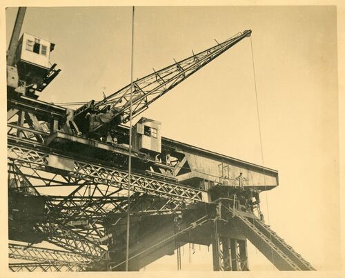
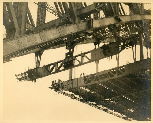
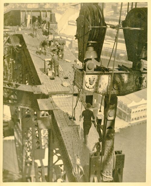
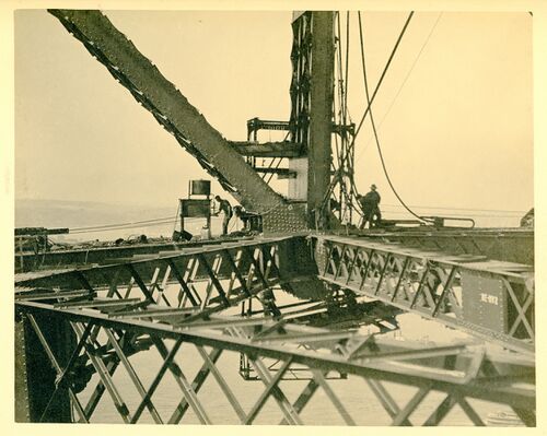
057 The front face of the chassis of the creeper crane extended past the arch trusses to that lifts could be made outside them. On the front face of the chassis a light (5 ton) walking crane traversed independently; it could slew but not derrick and could reach most positions in the panel ahead. It was used for minor lifts of men, stages etc. The verticality of the axle on which it slewed was changed whenever the creeper crane moved up or down the bridge, but provision was built in to allow this to be adjusted as required’.
The base of the huge creeper crane, with a lesser creeper crane attached to it.
058 The curved northern approach spans seen from between the abutment tower pylons. The road deck was finished first so as to create a working base for laying the four railway tracks. Surrounding the view are the timber trestle towers of the stiff-leg derrick crane building the above deck concrete and stone pylons. Comparison with photo 59 would suggest that this scene was captured in the early months of 1930.
059 The northern approach spans seen from deck level. By this time, late in the project, Bradfield would have substituted a reinforced concrete deck for the light-weight-concrete-filled steel troughing but Dorman Long, who were basically steel manufacturers, would not accept this change.
The roadway looking south - concrete will be placed into roadway to complete the job.
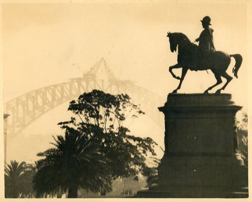
060 An artistic shot of the statue of King Edward VII – which stood in front of the Conservatorium of Music, with the bridge nearly lost in the fog in the background. The image must date from late August 1930 as the lower chords are joined but the top triangles not erected.
The bridge from Macquarie Street - an impression dominated by the statue of King Edward. The bridge from Macquarie Street - an impression dominated by the statue of King Edward.
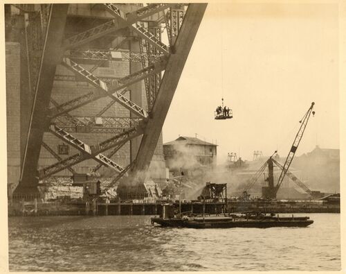
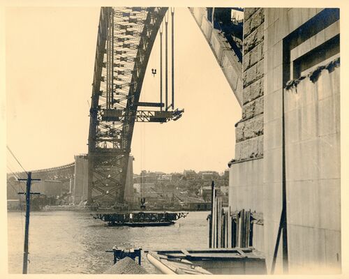
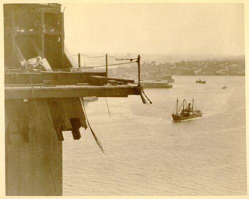
061An underside view of the Dawes Point end of the Bridge in January 1931. Men travelled to work on the bridge by launch to a punt moored directly below the point where work was underway and were lifted by the high-speed walking crane onto the arch. The building beside the abutment tower is Dorman Long's office.
January 1931
062 A view of Circular Quay from the incomplete deck near the centre of the bridge; this must be on the first deck section erected in September 1930. Note the unattached lower end of the next hanger at the left of the image. A single rope acts as a safety barrier at the deck edge.
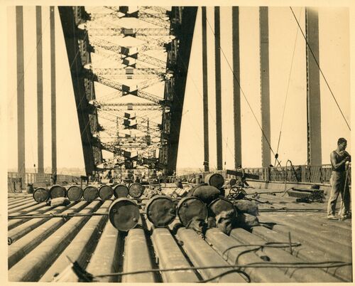
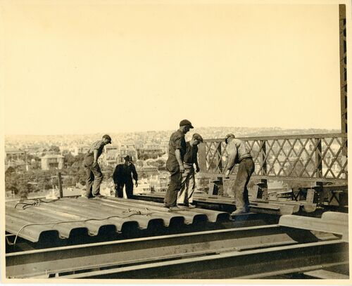
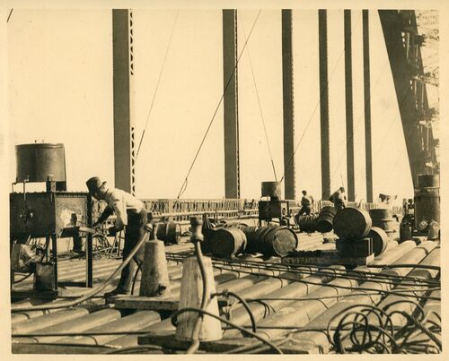
063 Oil drums for the riveting furnaces on the incomplete deck. Note the cable bracing, both transverse and longitudinal to secure the deck.
The Deck as it appeared before the concrete filling was placed in posiion.The drums in the foreground are oil drums for the rivetting furnaces.
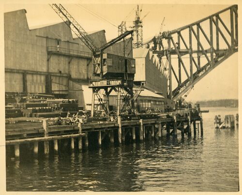
064 The wharf unloading and stacking crane at Milsons Point. Here ships from Middlesbrough and Newcastle (NSW) were unloaded. The workshop to the left is the light shop, two bays wide, for working plates and angles into bridge components. Above the workshop is the template shop. The workshop to the right is the heavy shop in a single bay, where complete and heavy fabricated bridge members were trial assembled with adjoining members before dispatch aloft.
Actually three workshops were built - The heavy shop - 500 feet x 147 feet; The light shop - 580 feet x 130 feet; The template shop = 300 feet x 130 feet; The heavy shops are served by two 120 ton capacity overhead electric cranes - the light shop by lesser cranes of similar type....
065 The last cross girder, on the northern side is in position, still held by the crane.
Last 100-ton cross girder going up on north side.
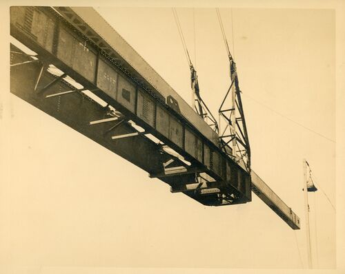
066 The shortest hanger being maneuvered into position. The creeper crane could not lift directly below the chord so a clever device had been designed to lift the long hangers eccentrically, but even more involved arrangements had to be made for the shortest hangers.
067 The shortest hanger being manoeuvered into position. The creeper crane could not lift directly below the chord so a clever device had been designed to lift the long hangers eccentrically, but even more involved arrangements had to be made for the shortest hangers. The hanger is fitted with a supplementary beam, wider than the bridge chord and the load is hanging from the main crane. A second rope, perhaps from the secondary jigger hoist on the main jib, has picked up the other end of the beam and will lift the hanger.
The last hanger going up. What a contrast to the first one. This little fellow only weighs a mere 7 tons.
C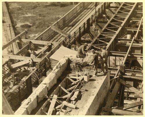
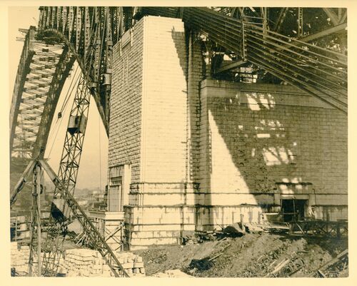
068 Once the abutment tower strong floor had been used as the base from which the creeper cranes were launched the two towers above deck level - the pylons could be erected, Early work on the abutment towers was undertaken by packing the stone and concreting behind them, but as stone production fell behind the structure was advanced as the bare concrete shell with the masonry cladding added as it became available. For the approach span pylons all the stone was on site so the older technique was adopted again. This image shows a stone being placed on the north-west pylon at Milsons Point. January 1931
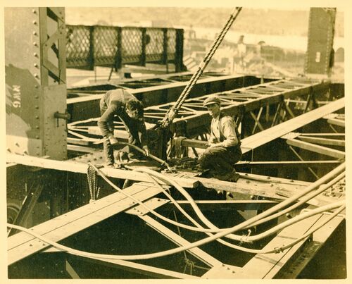
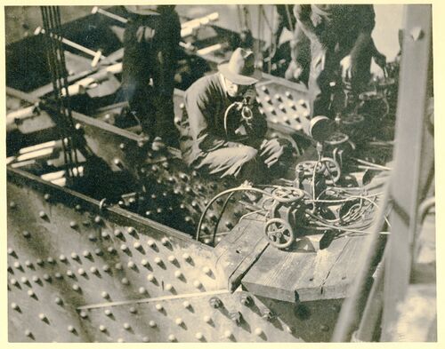
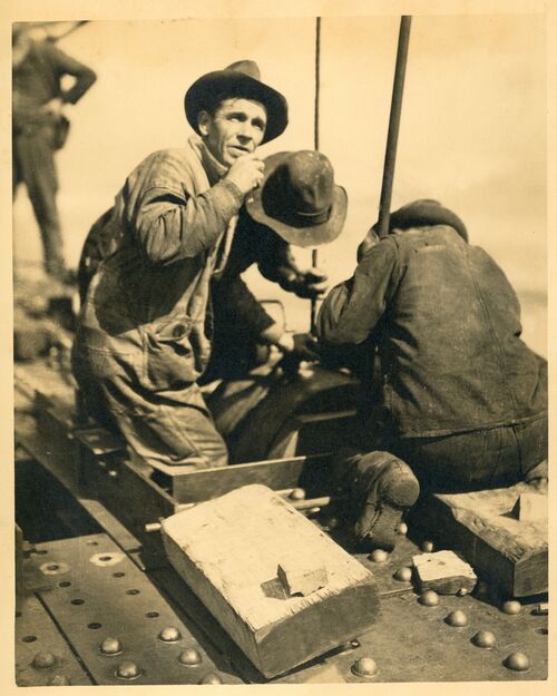
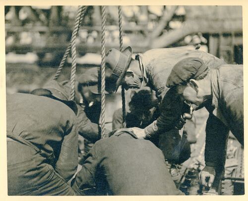
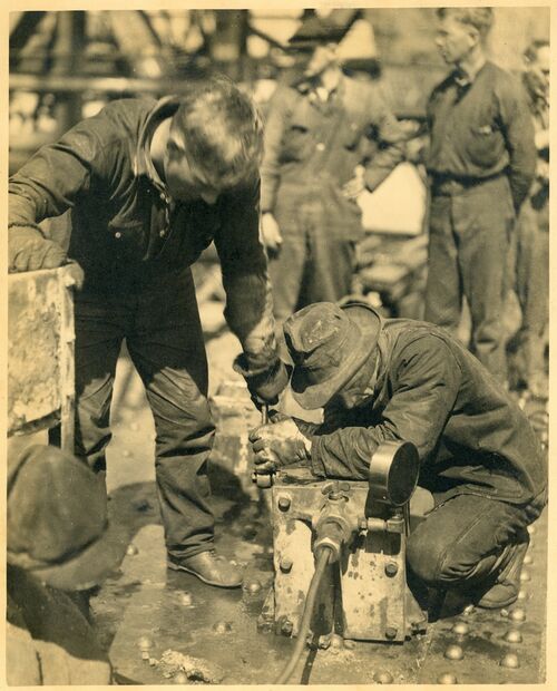
069 Mallard's caption suggests riveters but the tool in the hand of the man on the left seems more like a spanner. The large lines drooped about are certainly the delivery system for hot rivets.
Here you see the riveter at work. The lines leading to and past him are the tubes conveying the rivets.
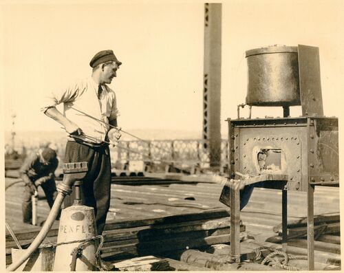
070 A worker heating rivets to white heat in an oil fired oven.
This was an everyday scene. White hot rivets had to be conveyed to all parts of the structure and conveyed expediently. Alongside the furnace a patent vacuum conveyer can be seen, the white hot rivets were placed into this and were immediately transferred by means of a flexible tube to the riveter.</small>
071 The deck of the traffic lanes of the bridge is heavy steel troughing filled and covered with light-weight concrete and an asphalt layer.
Troughing plates forming bedding for concrete and Neuchatel dressing.
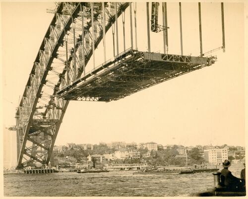
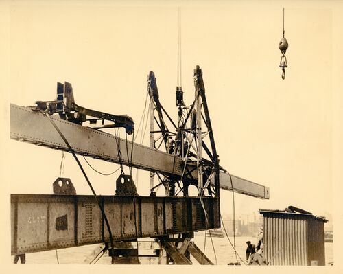
072 The deck was erected quite quickly after the arch was closed in August 1930. The creeper cranes built it from the centre outwards as they traveled back down the arch, By the end of 1930 it was nearly all completed so this scene must be in October or November. The western hanger of the fourth panel from the centre on the southern side is being erected using the offset lifting arrangement devised by Lawrence Ennis. Pontoons are anchored directly under the work sites as a base for work and an exclusion zone for harbour shipping.
Immediately the first pairs of hangers were erected, relief to the choked workshops came rapidly, piece by piece, every day saw the decking take shape. It is fitting just now to give you some idea of the huge weight that as gradually being hung from the arch. Altogether 13,500 tons of dead weight was placed into position, and by the way. when the traffic will be going over at peak periods, a further travelling load of 10,000 tons will be carried.
073 Three pairs of hangers and two cross girders in position, with the third cross girder on the barge about to be lifted. The cranes could lift maximum loads at ten feet per minute so the 200 foot journey will take a considerable time. The cranes could not lift these girders in their true positions as the cross members in the wind bracing of the top and bottom chords precluded the crane from occupying the ideal position. Once lifted the cross members were moved into proper alignment by block and tackle from the already erected deck. It was fortunate that the two cranes were available to lift the first cross girder as when lifting outside the plane of the main arch trusses the crane hooks could be perfectly placed. There was no already erected deck from which to pull the member into position.
The first three pairs of hangers in position.
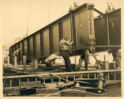
074 The western end of cross girder south 2 (SW2) on the pontoon about to be lifted. The staging for the workers to insert the connecting pin, high on the girder to the right of the light coloured brace, is already in place with the corresponding stage on the other side holding the pin.
Section of decking being maneuvered into position prior to hoisting.
075 Moving the second cross member on the southern side into position, for lifting it into place’.
Another view of decking member prior to erection.
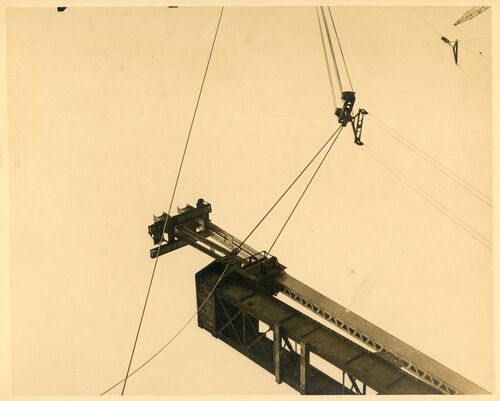
076 The crane hook could not access the location of the lattice girder pedestrian ways and the deck wind bracing chords on the edge of the deck. The crane could traverse cross the bridge and lift outside the truss, but not far enough to reach to footway. Accordingly, one of the railway stringers was pressed into service to be eccentrically loaded and lifted to gain the extra reach. This photo probably shows it being returned to the barge, mission accomplished, to be readied for the same job in the next panel.
A section of the railway permanent way being used as a carrier facilitating the hoisting of lesser members.
077 The crane hook could not access the location of the lattice girder pedestrian ways and the deck wind bracing chords on the edge of the deck. The crane could traverse cross the bridge and lift outside the truss, but not far enough to reach to footway. Accordingly, one of the railway stringers was pressed into service to be eccentrically loaded and lifted to gain the extra reach. This photo probably shows it being returned to the barge, mission accomplished, to be readied for the same job in the next panel.
078 A railway stringer being used to position a deck wind bracing chord otherwise beyond the reach of the crane or directly under the wide main chord.
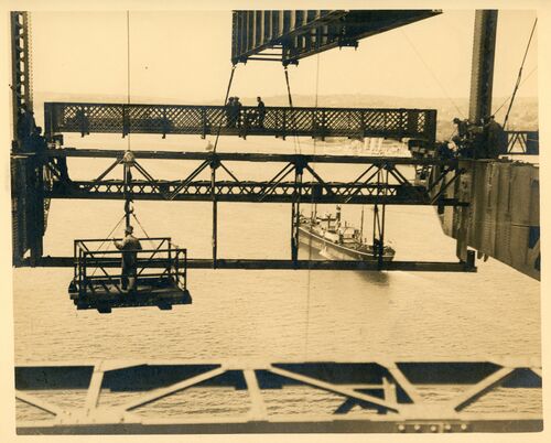
079 A railway stringer being used to position a deck wind bracing chord otherwise beyond the reach of the crane or directly under the wide main chord. A workmen's lifting cage is also in the scene, hanging from the walking crane.
Similar view to the last slide.
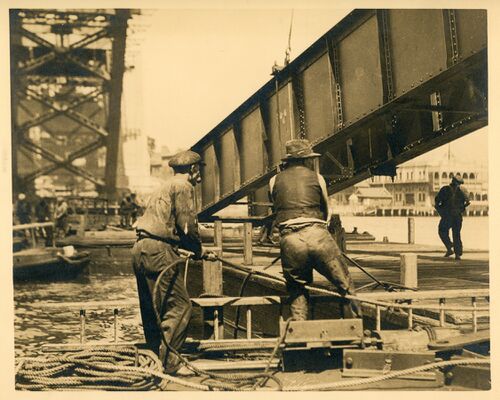
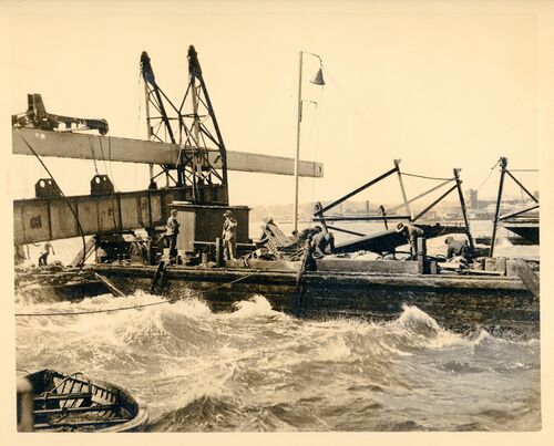
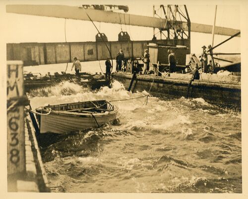
080 This and images 081, 082 and 083 illustrate the difficult and dangerous working conditions on a choppy day on the harbour. .. Preparing to lift a long hanger on a blustery day. The moored barges could be positioned more carefully using winches on the anchor lines’.
Fears of the anchor dragging keep these men busy at the windlass.
081 The barge has come out from the workshop with the hanger and moored to the fixed barge, waiting for the lift to start
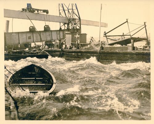
082 The water is quite choppy and the wind, preumably,quite strong making the lift risky and difficult.
083 Eventually the lift got clear of the pontoon and once high enough the hanger and its bracing frame rotated into the vertical. There is a rigger riding this load and he may be seen at the top, obviously well rehearsed at where to stand and move as his world rotates 90 degrees.
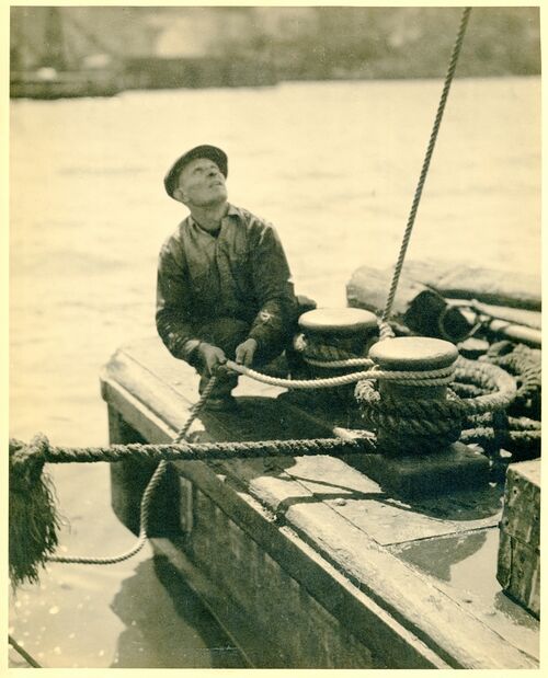
084 Mallard identifies this lift as the first hanger. The day is very calm so it may not be the day depicted in photos 80, 81 and 82. His explanation of the operation is all that needs to be said.
This workman appears interested in something up above. No wonder! The first hanger was going up and the rope he was paying out was giving the heights of the hanger from the punt so that the Erection Superintendent could give the signal for tilting the member into the upright position.
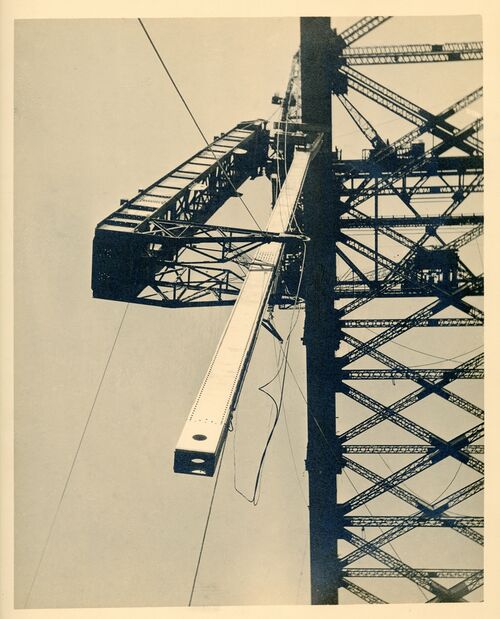
085 The lifting frame not only stiffens to flimsy tension member but allows the hanger to come up directly under the chord where it must be fixed. The crane hook alone cannot reach this point.
The first hanger in position. From the time it left the punt till it was pinned into position only 35 minutes were taken.
086 The first hanger going up.
087 The crane hook being moved into position to lift the first hanger. The Jigger hoist ropes are seen above the horn on the right. This small hoist will rotate the hanger in mid air.
088 The connection point at the top of the end post and end of the top chord after the cables and link plates have been removed. During the early stages of the erection the weight of the partly built half arch was difficult to balance against the force in the tie back cables, so a strut was provided to the strong concrete deck of the abutment tower.
089 The first hanger in mid harbour waiting to be lifted. The Jigger hoist is connected to what will he the lower end to effect the rotation.
To allow such a long member to be taken up a special cradle had to be made - here the hanger can be seen on its way lying in its cradle.
090 On at least one occasion the weather was too rough for the hanger lift so it was abandoned with the loaded barge moored safely against Milsons Point to await a better day.
The first and largest hanger ready for erection. Length 192 feet. Weight 37 tons.
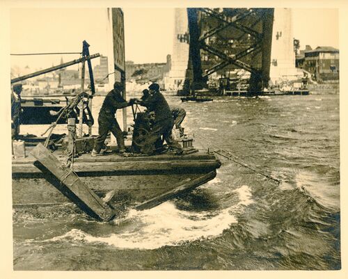
091 In a southerly blow difficulties are multiplied and an anxioius time is the lot of the Erection Superintendent. He can be seen shouting in the hope that the order will be registered in spite of the elements.
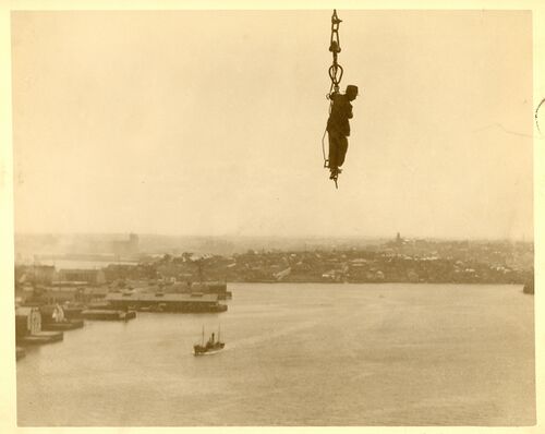
092 A Dogman many hundreds of feet in the air. This man went up and down every few minutes of the day without any fear of mishap. At times when a high wind was blowing he would be blown almost a right angles before he started to make his rapid descent.
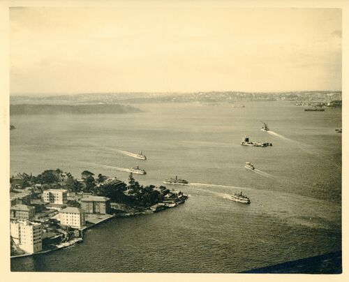
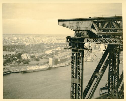
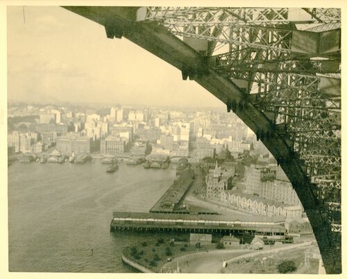
093 A view of Kirribilli and Admiralty House from the top of the creeper crane near the top of the bridge.
Sydney Harbour - view few have had the privilege to enjoy - from the creeper crane. The bridge can be seen in the immediate foreground.
094 The hauling gear of the creeper crane.
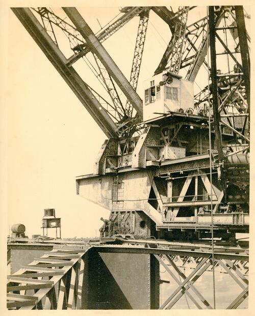
095 The driving position on the front of the one of the creeper cranes. Also seen is the 5 ton walking crane on the extreme right. The whole assembly of five cranes in one, dragged itself up the bridge on wheels, but lowered itself into direct contact to the chord to lift.
It is only fitting to tell you something of the two wonderful creeper cranes that we sa for so long piercing the sky, from which there was a sheer drop of hundreds of feet. Both these cranes were specially constructed for the specific work entrusted to them. They were colossal structures, weighing 560 tons each and with a lifting capacity of 120 tons.
096 Mallard photographed among the workers. Here he must be descending from the top of the arch in the stage hanging from the walking crane. The view is towards Circular Quay. A view coming down one of the stages.
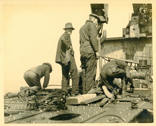
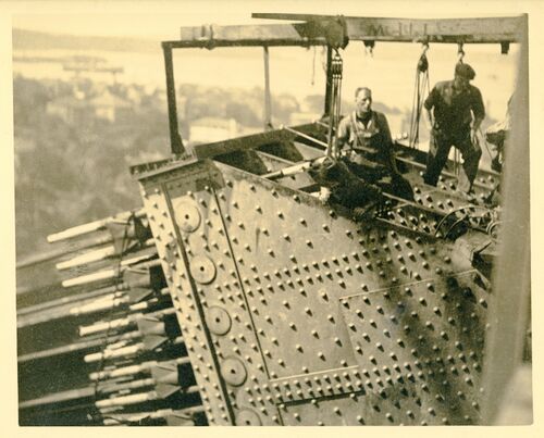
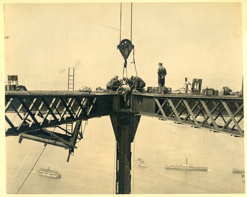
097 As preparation for joining the two halves of the arch, these these men are placing the bearing blocks or the jacks in the top chord so as to stress it to carry its share of the already erected dead load of the arch. September 1930.
Top chord workers - right at the crown of the arch.
098 As preparation for stressiing the two halves of the arch, hese men are placing the bearing blocks or the jacks in the top chord so as to stress it to carry its share of the already erected dead load of the arch. September 1930.
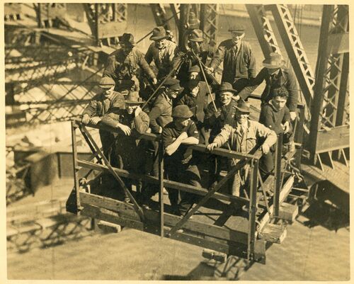
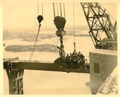
099 A sight seen many times during the day - men were transported in open cages and were quickly transferred to either the top chord or taken to the punt below in quick time. There was no limit to the number of passengers carried, so overcrowding was the rule - not the exception.
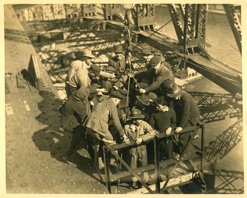
100 A sight seen many times during the day - men were transported in open cages and were quickly transferred to either the top chord or taken to the punt below in quick time. There was no limit to the number of passengers carried, so overcrowding was the rule - not the exception.
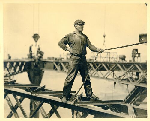
101 Typical bridge worker. This man, like many more, taking risks philosophically - a slip means, well, only a drop of437 feet. Why worry. There's work to be done.
102 As preparation for completing the arch, these men are placing one of the jacks in the top chord so as to stress it to carry its share of the already erected dead load of the arch. September 1930.
Another view of the jacks going into position.
103 Workers on a stage awating hoisting of one of the shortest hangers.
104 These men are placing one of the jacks in the top chord so as to stress it to carry its share of the already erected dead load of the arch. September 1930.
Placing hydraulic jacks in the top chord. These jacks exerted a pressure of 1,000 tons each. 28,000 tons of steel were slowly separated and allowed room for the last steel packing. When this was achieved the jacks were removed and the top chord was finally sealed.
105 Hand hydraulic pumps feed jacks with pressure of 1,000 pounds to the square inch.
106 The crown of the arch - 437 feet 6 inches from highwater mark - after the last panel had been closed. The top chord had to be separated to allow a steel bearing to be placed into position and also to make room for steel packing to allow for contraction and expansion. This picture shows engineers lowering the bearing into position.
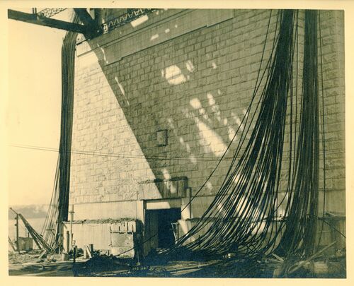
107 After the two half arches came into contact the tie-back cables were released as quickly as possible to avoid them contributing to the ideal distribution of load in the structure, pending stressing of the top chord.. Here many hang limp from the rear of the abutment tower awaiting spooling for resale and export.
The full length of the cables totalled 60 miles and weighed 3,300 tons.
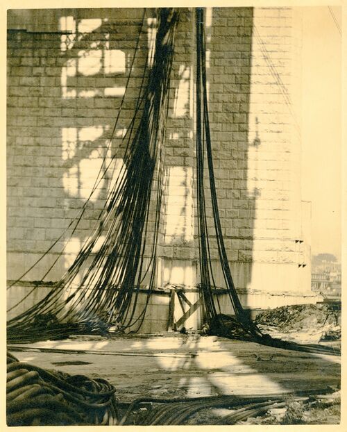
108 After the two half arches came into contact the tie-back cables were released as quickly as possible to avoid them contributing to the ideal distribution of load in the structure, pending stressing of the top chord.. Here many hang limp from the rear of the abutment tower awaiting spooling for resale and export.
After the closing up of both chords the cables had done their work and were lowered to the ground to be re-shipped to England. The tension on each of the 256 cables was 91 tons. At the closing of the bottom chord each cable took a strain of 108 tons - during that period each cable stretched 15 inches.
109 Looking down on the top chord, crown of the arch - 437 feet 6 inches from highwater mark - showing method of pinning, bolting and finally riveting the two halves of the chord together - main hoist gear in the foreground.
110 Looking down on the bottom chord, at the centre of the arch - 437 feet 6 inches from highwater mark - showing method of pinning, bolting and finally riveting the two halves of the chord together..
111 The first half of the top chord of the western truss of the northern half arch being lifted into position.
Closing the gap on the top chord - half a section of chord just placed into position, hoisting gear still attached.
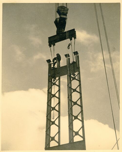
112 One of the centre posts of the bridge being lifted. This post was erected as two halves not laced together. Its two halves were correctly spaced where they were attached to the lower chord but too close together where they supported the top chord. When the top chords were forced apart during stressing the two parts of the post followed, becoming parallel and ready for lacing.
Section of the last upright going up to support the final piece of top chord.
113 A joint between lower chord, post, diagonals and lower chord wind bracing members near the top of the arch.
114 The centre joint of the eastern arch truss with the southern half of the centre post yet to be fitted. Also missing is the post of the lower chord wind bracing truss.
A more comprehensive view of the section before bolting, uprights and diagonals have been erected completing the bottom chord activities.
115 Rivet ovens on the deck of the bridge with drums of oil for their firing, pneumatic systems of delivery of white hot rivets.
Cookies help us deliver our services. By using our services, you agree to our use of cookies.


